
Part 2 – Circuit Design
Now that we know how a Cat5 cable works, we can design a circuit to test the cable. We do know that for straight-through cables we need to ensure 1-1, 2-2, 3-3, and 6-6. For crossover cables we need to ensure 1-3, 2-6, 3-1, and 6-2. We also need to test for shorts. That is, 1 cannot connect to 1 and 2. We want to be notified whether the successful test is for a straight-through or crossover cable by lighting an LED. Further, we want to simply plug in cables one after the other to test them. We don’t want to have to manually initialize the test.
One way to do this is to output a low on one of the four wires, one after the other, and leave the rest high. On the other end of the cable, make sure that only the designated pin is low and the others are high. Quite simple. If the test for straight-through fails, test for a crossover cable. When the test for either passes, light the correct LED. Note that to truly test a cat5 cable you need expensive test equipment that will ensure the cable can handle the data. This circuit just tests for correct wiring and identity, but does not determine if the pairs are twisted together correctly, etc.
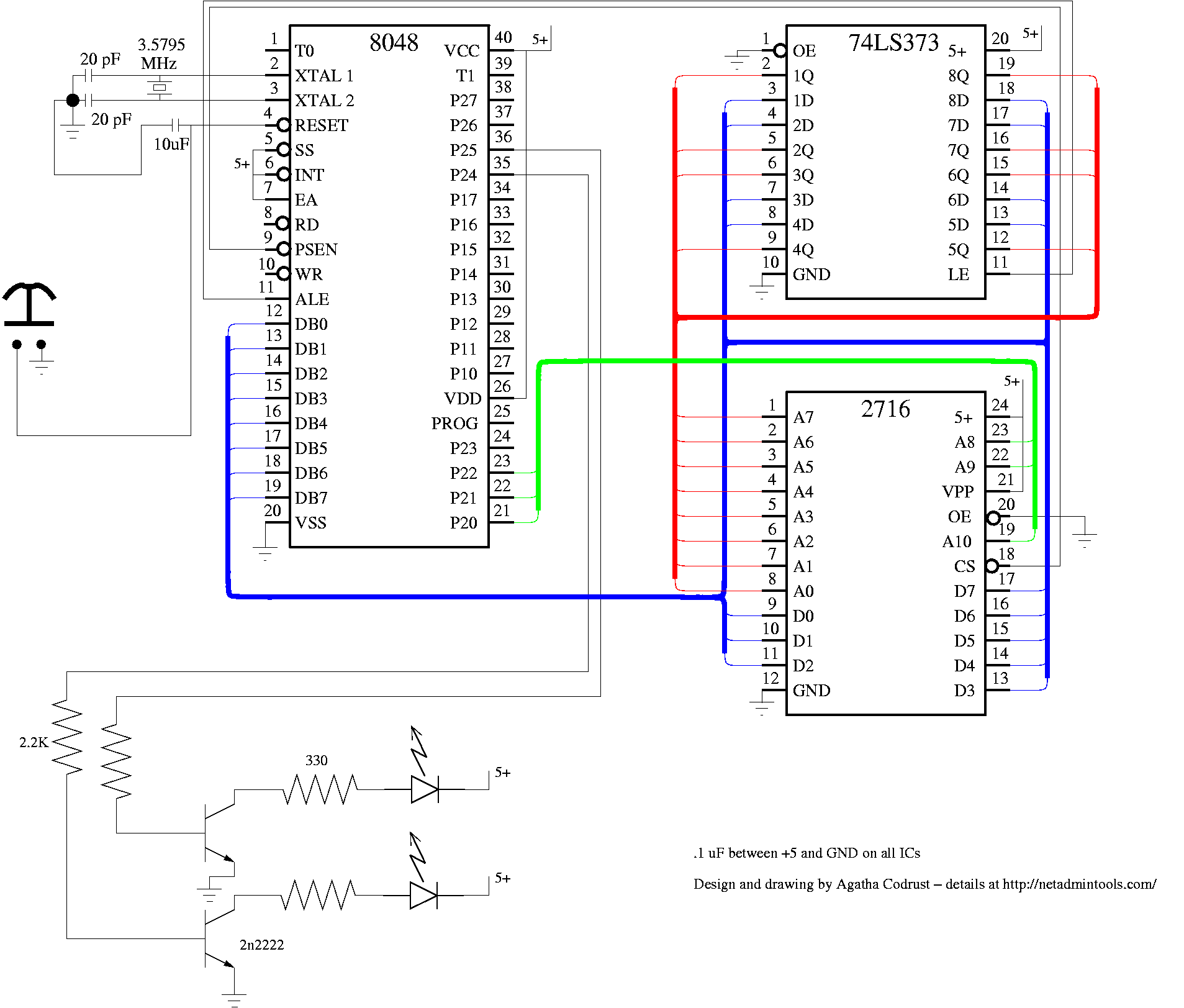
The most flexible circuit is a microcontroller-based circuit. We happen to have an 8048 development system and a lot of 8048s laying around, so that is what we will use for this circuit. Certainly a Basic Stamp or other PIC microcontroller would work as well. The only real need is 10 i/o lines. Here is a PDF of a schematic that will work for this (png version, fig file). If you would like to read the fig file using a Windows workstation, refer to this article. Port 1, bits 0-3 hook up to one cable, and Port 1, bits 4-7 hook up to the other. Two LEDs are driven by 2n2222a transistors, which are driven by bits 4 and 5 of Port 2 of the 8048. The 2716 is an EPROM memory that holds our program, and the 74LS373 is a latch for the lower 8 bits of the address.
The program for this device is written in assembly language. Here is the assembly language listing. At 0, we light both LEDs by writing a hex 30 to port 2. This turns on bits 4 and 5. We then delay for awhile by loading FF in to register a and decrementing until we get to 0. To test pin 1, we write an FE to port 1. This makes pin 1 of the Cat5 cable low, and the others high. When we read back this data on bits 4-7 of port 1, we should see EE. We test the other three pins in the same way. The 8048 has a small instruction set, so there is no compare instruction. To test for EE, you have input the data from port 1 to the accumulator (in a,p1), complement the accumulator (cpl, a turn 1s to 0s, and 0s to 1s), add the number you want to compare to, and then take the complement again. As an example, take binary 6 (0110). If we want to check if it is 6, we complement it (1001), add 6 (1111), and complement it again (0000). The accumulator is now 0, so we can jump based on that flag. In the case of EE, if the result is not 0, we jump to X0080 (jnz X0080). X0080 is where we check for a crossover cable. If any test for straight through fails, the program jumps to the crossover test. If either pass, the program sets the correct LED by outputting a 10 or a 20 to port 2. Finally, if neither matches, both LEDs are turned off, and the tests start again.
Here is a picture of the 8048 dev system running the program to turn on the “S” and “X” LEDs
Here is the emulator program running Notice that we are about to have a match for a crossover cable for pin1. The asterisk is the current command. Port1 is BE. We have added BE, and are about to take the complement. After adding BE, the accumluator is FF, so we do indeed have BE on port1 after writing FE to the port at address 082.
There are five parts to this article:
Build Your Own Cat5 Cable Tester – Introduction
Part 1 – How to wire Cat5 cables, and how they work